Concrete Investigations with GPR
With 24/7 global construction and ageing infrastructure, the demand for concrete inspection, structural assessment, and targeted repair has never been greater.
The Questions Every Engineer Needs to Answer Before Drilling
Engineers, contractors, and facility managers are increasingly asking the same critical questions:
- Does this structure require immediate maintenance, or can repairs be scheduled in 12 months?
- Can we safely cut or core through this concrete slab without hitting rebar or embedded utilities?
- Is there sufficient reinforcement to support an additional storey or increased floor loading?
- Where are the electrical conduits, water pipes, and post-tension cables – and where is it safe to drill?
The Problem with Traditional Concrete Investigation
Traditionally, answering these questions meant destructive testing: cutting, coring, or breaking open the concrete to see what lies beneath. This approach carries serious risks. Drilling blindly into a reinforced concrete structure can compromise structural integrity, damage critical utilities, and trigger failures that are costly – or catastrophic. When a severe structural failure occurs, the consequences go far beyond the financial.
A Smarter Way to See Inside Concrete
That’s why the industry is rapidly shifting toward non-invasive concrete investigation techniques, with Ground Penetrating Radar (GPR) scanning leading the way.
What Can GPR Detect in Concrete?
GPR allows engineers and surveyors to see inside concrete without a single cut, including:
- Rebar position, depth, and spacing
- Post-tension cables and pre-stressed tendons
- Voids, delamination, and honeycombing
- Embedded pipes, conduits, and utilities
- Slab thickness and layer boundaries
All of this is captured in real time, on site, with zero structural disruption.
When Should You Consider a GPR Concrete Survey?
GPR scanning is the right solution when you need to:
- Core or cut safely without risking rebar or utility strikes
- Assess structural capacity before increasing loads or adding storeys
- Investigate suspected deterioration or hidden damage
- Plan refurbishment or demolition works with confidence
- Comply with safe digging and pre-drilling survey requirements

Fast, Accurate, Non-Destructive – The Future of Concrete Investigation
Whether you’re managing ageing infrastructure, planning a major refurbishment, or simply need to drill safely, GPR scanning delivers the sub-surface insight you need – without compromising the structure you’re working on.
Method
Using GPR to investigate concrete and rebars
GPR (Ground Penetrating Radar) is a non-destructive investigation method that uses electromagnetic pulses to produce an image of the subsurface.
This can be achieved without drilling or otherwise impacting upon the structure’s integrity. Whilst also providing better data coverage compared to the more traditional point-by-point invasive tests, GPR is considered a cost–efficient investigation technique, with practically no risk of damaging or destroying the investigated material.
Locate Targets in Concrete with accuracy
GPR can be compared to a fish-finder (or echolocation device) on a boat. A transmitter antenna sends a pulse into the concrete (in this case), and that pulse reflects whenever there is a contrast in the dielectric properties of the medium it’s being sent into.
Using the right technique
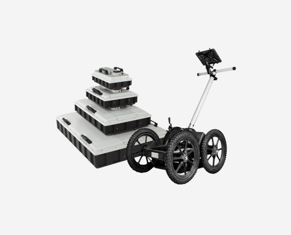
Investigation can be done on both horizontal and vertical surfaces, where the antenna is swept over the areas to be investigated in a structured way. Single lines can be measured for layers or several lines for 3D results of more complicated structures. For floor investigations there are ergonomic handles available or the antenna can be placed in a cart.
GPR antenna frequency and estimated resolution and depth
What frequency to use depends on the application, and what resolution and depth is required. For concrete constructions and rebars frequencies around 750 MHz to 2.3 GHz are quite convenient.
| Antenna Frequency (MHz) | Suitable Target Size (m) | Approx. Depth* (m) |
| 800/750 | 0.03 | 2.5 |
| 1200 | 0.02 | 2 |
| 1600 | 0.015 | 1 |
| 2300 | 0.01 | 0.85 |
Frequency is not the only factor that determines the achievable depth and resolution; the concrete through which the signal is sent also determines the quality of the collected data.
Most often a moist, newly laid concrete is hard to investigate with GPR as the conductivity is too high and the electromagnetic pulses will be attenuated rapidly. If you have several layers of rebar, the top ones will most likely disturb the results from the lower ones.
Different GPR applications for concrete and associated structures
There are a number of different applications where GPR can be most useful within the application area of concrete structures and rebar:
- Mapping of rebar, reinforcement, tendons etc.
- Detecting conduits such as heating pipes and other utilities within the concrete structure
- Recording concrete thickness
- Mapping of layers in the concrete such as isolation, sandwich elements etc.
- Detection of cracks and voids
- Mapping of water saturation/moisture and corrosion
Projects marked directly on site – “mark out”
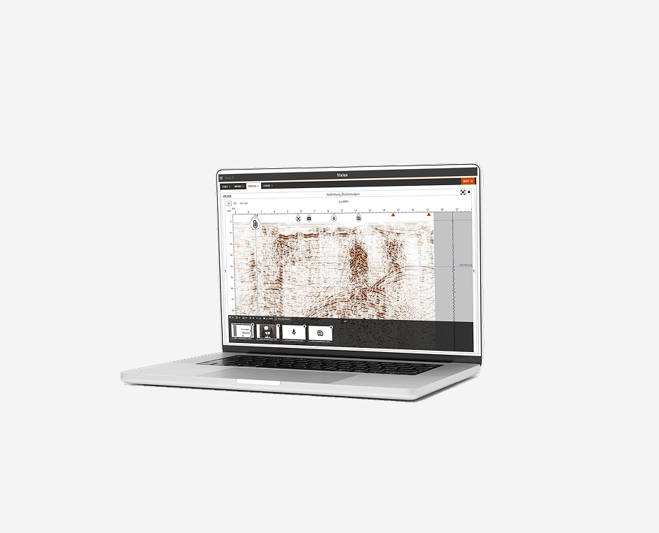
With MALÅ concrete and rebar solutions, work can be done efficiently, and the results presented directly on site. Rebar particularly are often clearly identifiable on screen in real-time and, with the easy ‘back-track’ option on the GPR system, the location of the rebar can be directly marked.
Direct marking on site. In this project concrete grouting was needed in older concrete walls and, to avoid drilling into the larger load-bearing reinforcement, GPR was used to mark these directly on the wall. Note! In the example raw GPR data are shown, with no processing, as it was only important to see the location of the larger reinforcement below the dense net of smaller bars.
Projects analysed after the survey – “post-processing”
MALÅ concrete and rebar solutions also provide efficient data collection and storage for further processing at site or back at the office. If rebar, and perhaps utilities (such as heating pipes), are organized in nets and possibly at several depths, for example, this is the most convenient way of working: data collection in systematic parallel lines in one or two directions for later analysis and detailed mapping. This can include 3D investigations with single channel or multi-channel array options.
Direct marking on site. In this project concrete grouting was needed in older concrete walls and, to avoid drilling into the larger load-bearing reinforcement, GPR was used to mark these directly on the wall. Note! In the example raw GPR data are shown, with no processing, as it was only important to see the location of the larger reinforcement below the dense net of smaller bars.
In the example a smaller area has been investigated with parallel lines in two directions. The processing is made in the data collection unit or in a computer. The result is displayed as a 3D volume, showing the investigated area at different depths, in so–called times slices. Note that one layer consists of larger but sparsely situated bars and the other layer of smaller more densely placed bars