In principle, Borehole GPR is identical to surface GPR measurements. The main difference is that the media to investigate normally surrounds the antenna making results somewhat more difficult to interpret. The GPR antennas are also built to fit into a borehole and includes a waterproof casing to cope with the increasing water pressure at depth.
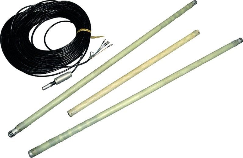
A borehole GPR system consists of:
- Receiver antenna (Rx).
- Transmitter antenna (Tx).
- Fiber optic cable for data transmission.
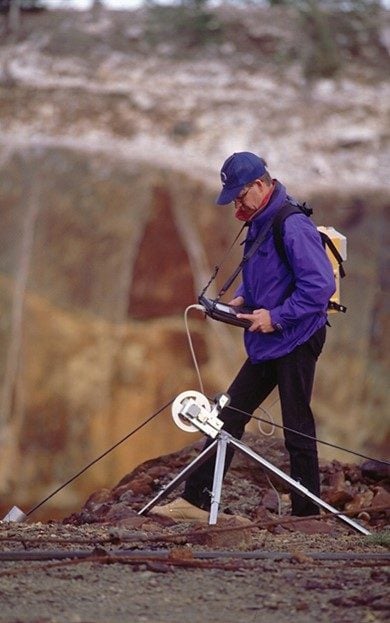
- Tripod with encoder. The tripod makes the lowering and lifting of the system easier.
- Control unit taking care of transmitting and receiving the electromagnetic pulses to and from the antennas.
- Montitor/PC for data collection.
The most used type of antennas for borehole measurement are standard omni-directional dipole antennas, which radiate and receive reflected signals from a 360-degree space.
The standard borehole system is built and tested down to 200 m water pressure, but Guideline Geo can customize solutions for much higher water pressure if needed.
Borehole GPR measurements are often carried out in three different modes, reflection, cross-hole, and surface to borehole.
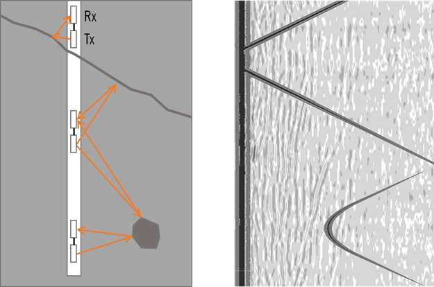
Reflection mode
Reflection mode (also called dipole measurements) the radar transmitter and receiver probes are lowered in the same borehole with a fixed distance between the Tx and Rx, as an ordinary 2D ground measurement. Reflection mode is used to map the distance to reflectors (as fractures, cavities, boulders) and in the case where the reflector is a plane (as a fracture, tunnel, borehole), the angle between the plane and the borehole can be determined.
Reflection mode
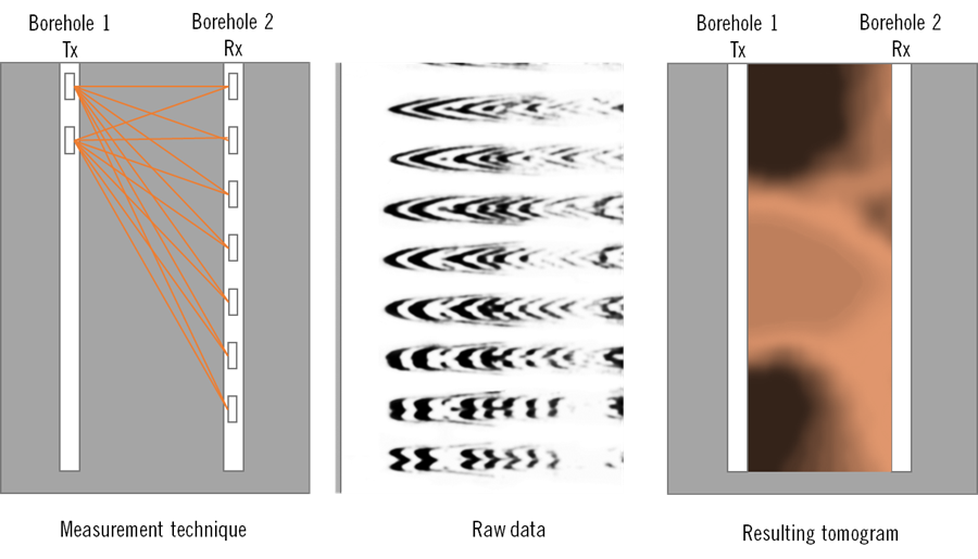
Cross-hole mode
In Cross-hole mode (or tomography measurements) the transmitter and the receiver are lowered into different boreholes. The plane between the boreholes is investigated by acquiring radar transmissions along multiple ray-paths across this plane. Tomography inversion can be made both for amplitude and the travel time of the first arrival. Travel time tomography can indicate higher water content in the media (e.g. water filled fractures and cavities) because the velocity of the radar signal is strongly affected by the high dielectric constant of water. Amplitude tomography is used to determine attenuation of the radar signal and can be used to map the presence and distribution of contaminants and water in fractured rock.
Cross hole mode
Surface to borehole
In surface to borehole mode, one borehole antenna is placed on the surface, and positioned at different distances from the borehole and one borehole antenna is lowered into the borehole. It is possible to compile amplitude and velocity tomographic images of the plane between the borehole and surface antenna positions. Planes like this can be created in various directions depending on the location of the surface antenna.
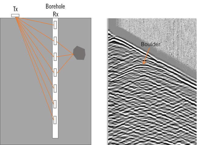
Surface to borehole
For borehole GPR investigations it is also important to remember that:
- Measurements can’t be made through a metal casing. Plastic/PVC casing is ok.
- If the borehole is waterfilled, the conductivity of the borehole fluid should not exceed 50 mS/m.
More to read
Application areas
https://www.guidelinegeo.com/application-areas/
Methods
https://www.guidelinegeo.com/ground-penetrating-radar-gpr/
Case Stories
https://www.guidelinegeo.com/solutions/case-stories/
Products
https://www.guidelinegeo.com/mala-ground-penetrating-radar-gpr/