Bedrock Investigations with Geophysics
Bedrock is the hard, solid rock most often found beneath unconsolidated surface materials such as sand, clay, or till, but it can also appear as outcrops above ground. When finding bedrock using geophysical methods the depth to the rock head can vary from zero to several hundred metres, and both the topography and quality of the bedrock may differ significantly.
Understanding bedrock conditions is essential for a wide range of human activities. Knowledge of the depth to bedrock and its properties is critical for:
Infrastructure projects – ensuring safe and stable construction of buildings, bridges, roads, railroads, and airports. Aside from safety concerns, failing to determine bedrock depth or quality can cause severe cost increases and large project delays.
Tunnels and repositories – planning and constructing tunnels, storage facilities, or wells in the bedrock.
Resource extraction – locating and characterising mineral resources (e.g. iron, copper, gold), aggregates, and fossil fuels (e.g. coal, oil, and natural gas).
Groundwater studies – characterising aquifers in bedrock formations, such as porous sandstone or fractured crystalline rock.
Water management and climate adaptation – mapping areas suitable for storm-water management in response to increasing precipitation.
Contaminant studies – tracing groundwater pathways and understanding how contaminants may move through fractured rock.

Traditionally, bedrock investigations have relied on drilling or excavation. While these methods provide direct information, they are costly, time-consuming, and offer limited spatial coverage. In addition, the modern subsurface is becoming increasingly crowded with infrastructure, making intrusive methods both risky and sometimes impractical.
This is where geophysics provides powerful, non-destructive alternatives. Methods such as seismics, electrical resistivity tomography (ERT), ground penetrating radar (GPR), and Transient electromagnetics (TEM) can be used to map the depth, structure, and properties of the bedrock. These tools make it possible to:
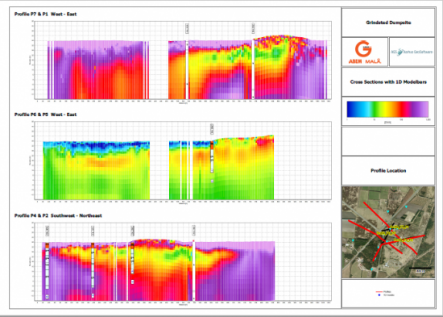
Create 2D and 3D models of bedrock topography.
Identify fractured or weathered zones that affect stability or groundwater flow.
Assess variations in rock quality for construction or resource extraction.
Collect continuous datasets over large areas, reducing the need for dense drilling.
By integrating geophysical methods with selective drilling, a far more comprehensive and cost-efficient picture of the subsurface can be achieved. This approach supports safer infrastructure design, optimised resource exploration, and better environmental management.
Geophysical Methods for Finding Bedrock
Finding Bedrock using Geophysical Methods is something several of Guideline Geo´s wide range of geophysical investigation techniques can solve. Although in different ways. They will give a non-destructive and cost-efficient way of gaining a better understanding of the ground conditions, providing better data coverage than is normally achieved with traditional, discrete, point-by-point geotechnical investigations, such as drilling or digging.
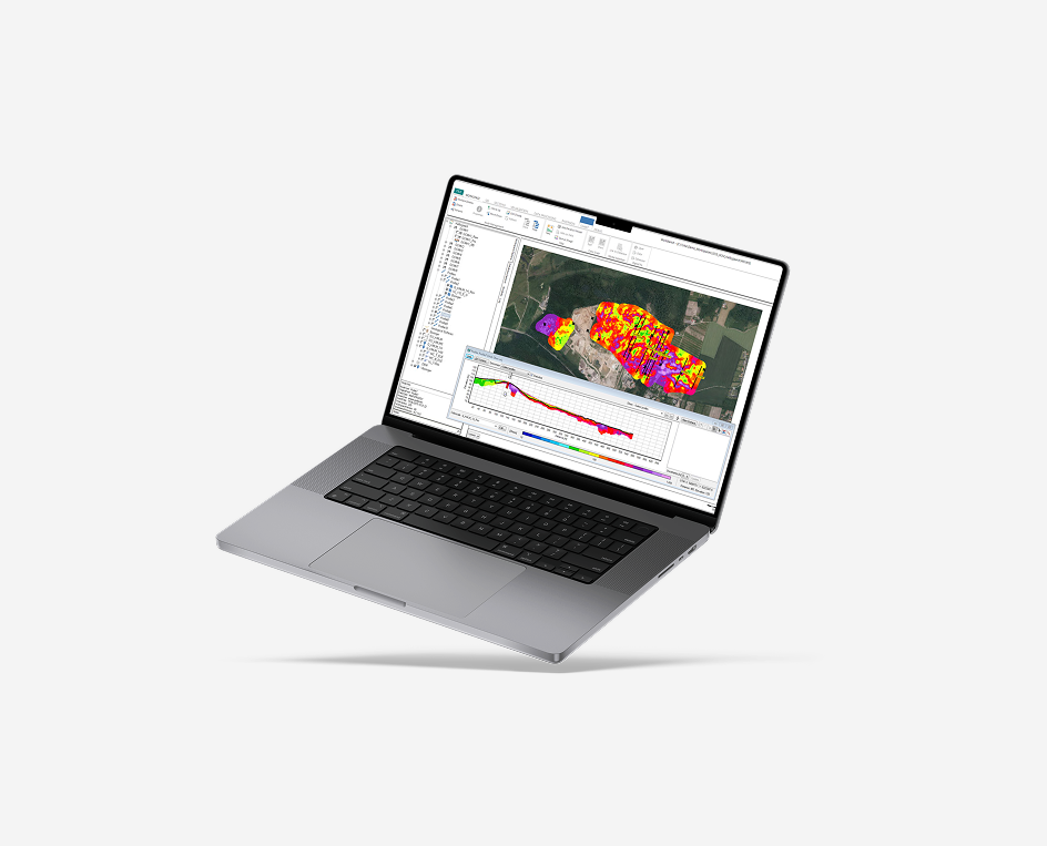
In Table 1 the most common bedrock applications and a range of possible geophysical techniques for their investigation are listed. Guideline Geo provides both GPR, resistivity, seismics and TEM solutions for bedrock investigations. Note that all solutions provide output as position (XY) and depth (Z) against some other parameter such as depth to bedrock, which can be transferred easily to GIS or CAD applications.

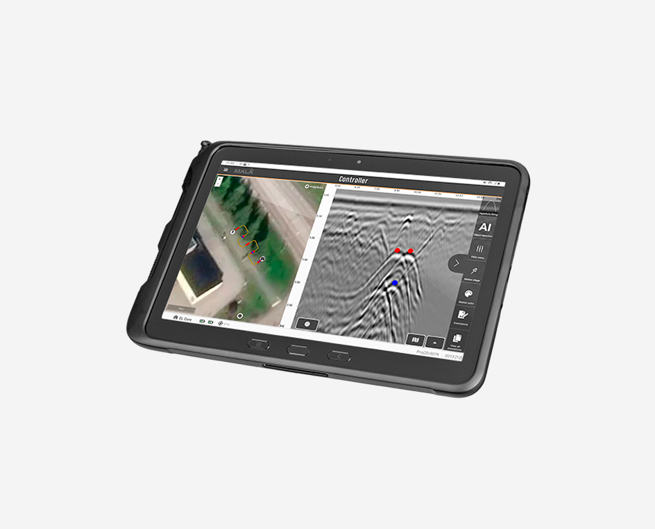
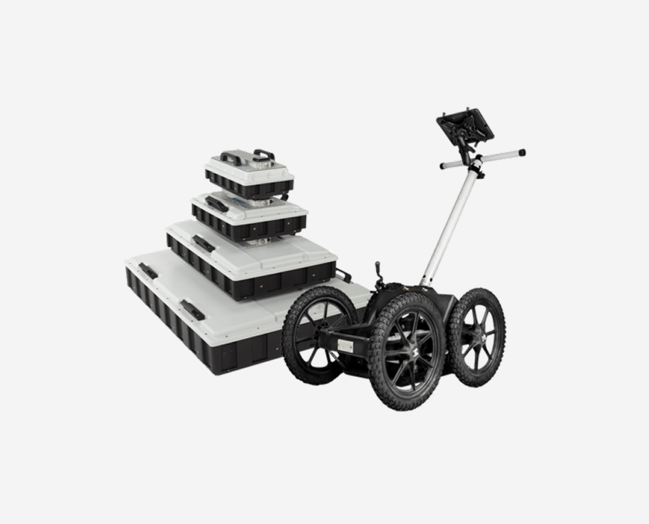
Ground Penetrating Radar for Finding Bedrock
GPR is suitable for:
- Bedrock level / detection
- Topography of bedrock surface
- Cavities within the bedrock
- Fractures in bedrock (from the surface, from within boreholes, or inside tunnels e.g. walls and roof)
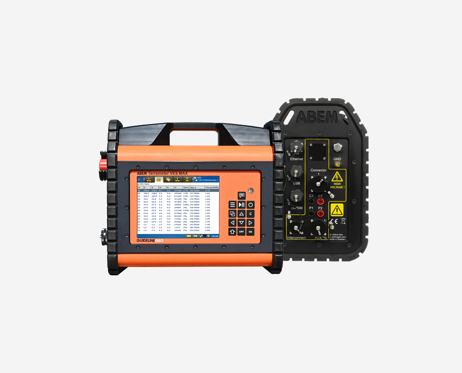
Resistivity for Finding Bedrock
Resistivity is suitable for:
- Bedrock depth / detection
- Bedrock topography
- Fracture and fault zone identification
- Cavity detection and mapping
- Ores / mineral deposits
- Lithology or bedrock type / change
Seismics for Finding Bedrock
Seismics is suitable for:
- Bedrock depth / detection
- Bedrock topography
- Fracture and fault zone identification
- Cavity detection and mapping
- Lithology or bedrock type / change
- Mechanical (engineering) parameters
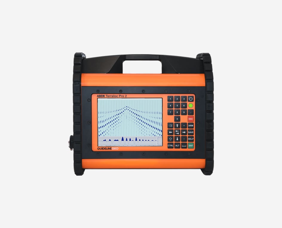
Guideline Geo’s ABEM Terraloc products are incredibly versatile and can be configured to undertake practically any type of seismic data acquisition; the only choice is the scale of system in terms of how many measurement channels are required. A very wide range of 3rd party processing packages available from Guideline Geo ensures that the perfect solution can be found for your particular application.
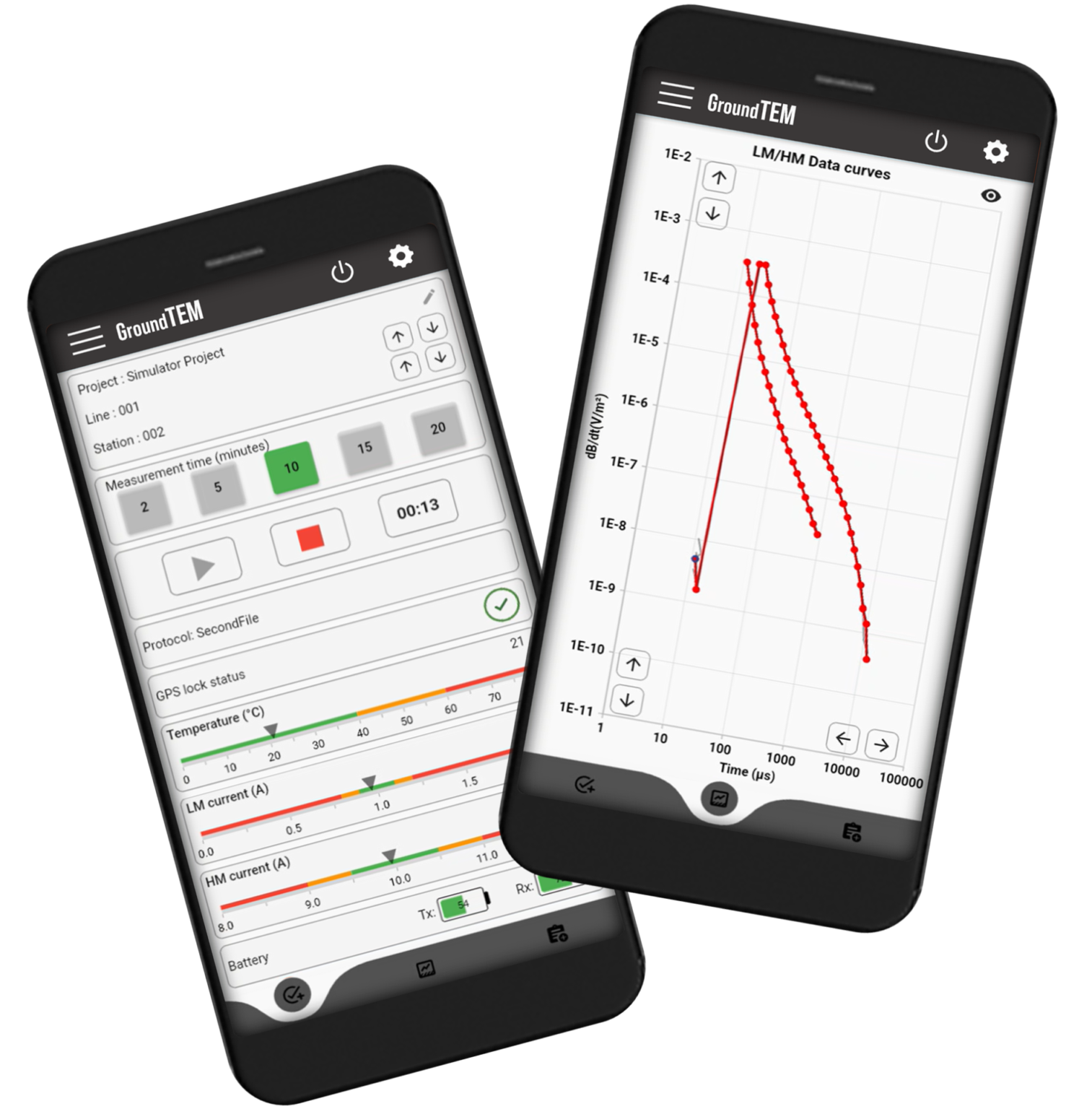
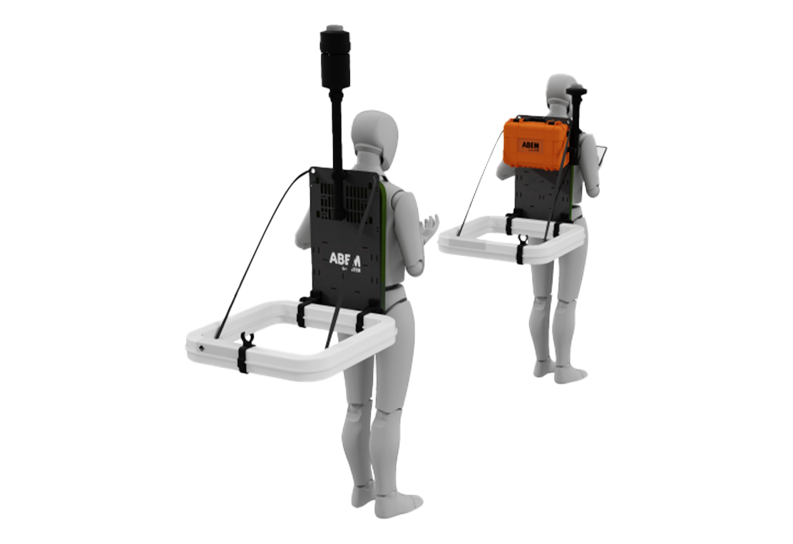
TEM for Finding Bedrock
TEM is suitable for:
- Bedrock depth / detection
- Coarse bedrock topography
- Ore / mineral deposits
- Bedrock type / change
What method and technique to use?
When it comes to finding bedrock using geophysical methods there are many factors involved in deciding upon the correct solution for a given project, these are some of the key considerations:
- GPR is suitable in non-conductive conditions (e.g. without clayey soils) down to approximately 30-50 meters
- TEM is unsuitable in urban areas due to sources of electromagnetic disturbance
- TEM is suitable for deep investigations (>500 m) where resistivity and seismic methods might be limited by access, equipment power or general survey practicalities
- Resistivity requires galvanic contact via electrodes of some description which can be both hard and time consuming in environments with bare rock or asphalt etc.
- If an active (as opposed to passive) seismic method is to be employed the source needs some consideration; it needs to be big enough to get the energy to and from the desired depth and there may be legislative or environmental constraints upon how this is achieved
- TEM or VES may be sufficient for broad prospection but GPR, ERT and seismic methods are best for more detailed results
- Seismic methods can provide quantitative appraisal of geological strength and stability
- TEM is not well suited to differentiating between highly resistive geological units; the method responds better to conductive stratigraphic elements
- 1D methods (VES, TEM, VSP) are not well suited to identifying confined features like fracture zones and intrusions compared to 2D methods which offer lateral detail
Combining methods
It is often beneficial to combine different geophysical methods to get the best resulting picture of the bedrock conditions due to the overburden conditions, the physical distribution of the bedrock or level of information required. For instance:
- if the project covers a wide geographical area, GPR can be used more efficiently in highland areas with till and sands, whilst resistivity investigations may be more successful in lowland areas with high proportions of clay and silt
- it may be beneficial to supplement ERT or seismic methods with TEM soundings through those areas where the bedrock was too deep to be detected by the primary methodology
- GPR can give excellent detail on the stratigraphy, where the interfaces between geological units lie, but a method which gives a more quantitative result (such as resistivity or seismic refraction) can aid with the interpretation of what material makes up each of those units.