What are seismic methods?
Seismic methods record the movement of vibrations through the ground with their speed and path telling us something about the structure, strength and/or stability of the subsurface.
All seismic systems require three components: a source (either user-generated or naturally occurring vibrations), sensors and cabling to detect the seismic waves as they move through the subsurface (geophones on land, hydrophones in water) and an instrument (seismograph) to record that motion for later analysis.
When should you use seismics?
When you have a need for a non-destructive investigation technique for subsurface conditions, seismics can be a good alternative to provide a more comprehensive picture compared to traditional intrusive methods, such as digging and drilling.
The comparative strengths and weaknesses of the seismic method
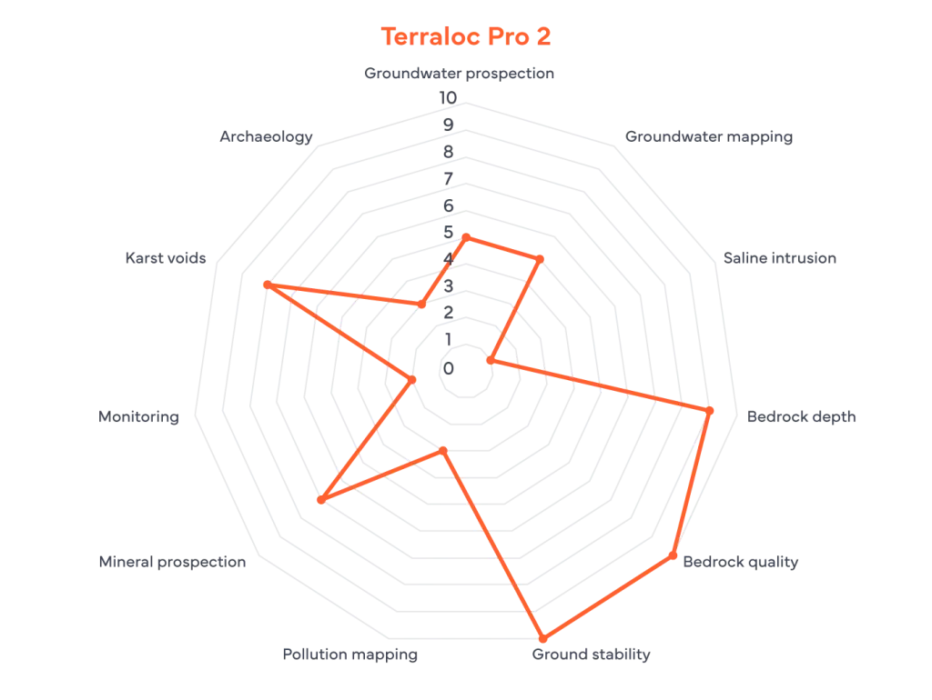
Seismic methods are excellent for determining ground stability (10/10), mapping depth to bedrock (9/10), and evaluating bedrock quality (10/10). If your project involves foundation engineering or quarrying, this is the ideal methodology for the job.
It also performs exceptionally well in detecting karst voids (8/10) and well in assisting in mineral prospection (7/10), providing reliable data where subsurface gaps or ore bodies create distinct seismic signatures.
While seismic can be used for groundwater prospection and mapping, it is typically utilized as a complementary tool in these fields to provide structural context for hydrological data.
Conversely, seismic methods are rarely the primary choice for saline intrusion or monitoring, where electrical signatures are significantly more prominent and easier to detect than acoustic ones.
Common applications for seismic methods
- Bedrock detection and topography
- Mechanical parameters (rock strength, soil stability, rippability etc.)
- Earthquake resilience studies
- Fractures and fault zones
- Cavities
- Lithology or bedrock type
- Mineral and oil prospection


How does it work?
Some form of energy source transmits elastic waves through the ground, which are then recorded by a seismograph via a set of geophones or hydrophones. The speed and path of the waves is controlled by the density, elasticity, and structure of the ground. By recording the movement of these waves with our seismic equipment and analysing their speed and nature, a model of the sub-surface structure can be produced. The seismic velocities of individual layers can help to predict the type of material present as well as its strength and/or stability. Typically, faster velocities indicate stronger or more stable materials.
Depending upon the type of accessories and survey procedure used, different types of motion can be recorded. Common modes of seismic survey include refraction, reflection, surface wave and borehole all of which are discussed briefly, below.

Refraction
Refraction has a relatively simple field procedure and is well suited to mapping bedrock location, topography, and strength as well as general geological sequencing. The processing is also relatively straightforward and only looks for the first seismic arrival at each sensor. It relies on the fact that seismic velocity of the layers being investigated increases with depth, thus energy that has travelled through deeper layers will ‘overtake’ energy travelling through slower shallower layers and arrive first at more distant geophones.
Inversion software is used to find a combination of layer thicknesses and velocities which provides modelled data close to the ‘real-world’ recorded data.
A rule of thumb for designing a refraction survey is that the cable spread should be 3 – 5 times longer than the depth required, but consideration should also be given to the energy available from the source.

Reflection
Refraction has a relatively simple field procedure and is well suited to mapping bedrock location, topography, and strength as well as general geological sequencing. The processing is also relatively straightforward and only looks for the first seismic arrival at each sensor. It relies on the fact that seismic velocity of the layers being investigated increases with depth, thus energy that has travelled through deeper layers will ‘overtake’ energy travelling through slower shallower layers and arrive first at more distant geophones.
Inversion software is used to find a combination of layer thicknesses and velocities which provides modelled data close to the ‘real-world’ recorded data.
A rule of thumb for designing a refraction survey is that the cable spread should be 3 – 5 times longer than the depth required, but consideration should also be given to the energy available from the source.

Surface wave
With surface wave methods, again, the aim is to generate a model of velocity variation rather than a reflection-style, detailed image of stratigraphy. The field methodology will vary depending upon the method employed. But the output is generally a 1D, 2D or 3D model of shear wave velocity which gives an excellent indication of a material’s stability and can be used in widely-published formulae to generate quantitative engineering parameters.
For active surface wave methods, the rule of thumb for depth capability is that the cable spread should be 1 – 2 times longer than the depth required.

System design
A key requirement for collecting good data is a suitable seismic source; one which is powerful enough to generate detectable waves all along the survey spread and to the required depth. The frequency signature of the source is also important: something which generates more high-frequency energy will result in greater detail, but the signal will be attenuated (absorbed) much faster; a low frequency source will provide good depth penetration, but resolution is compromised. With vibration sources (as opposed to impact sources like a hammer or weight-drop) it is possible to define the specific vibration frequency, or even choose a “sweep” of frequencies from high to low. Use of a vibration or impact source defines “active” methods, but in “passive methods” the source is background vibrations originating from both natural and human motion (such as tides, distant tectonic activity, construction, traffic). These are very low frequency but very powerful vibrations, typically used in surface wave studies.
Geophones will need to be matched to the task in hand and are normally defined by their orientation and their “Hz” rating, which defines the frequencies they are most sensitive to. As with sources, low frequency units respond well to energy that has likely travelled further into the ground, whilst their higher frequency counterparts will be able to deliver better detail. Some methods need lower frequency units, such as any surface wave analysis, whilst others like reflection can benefit from those with a higher rating. As for orientation, refraction studies normally require vertically mounted sensors, reflection surveys often use horizontally orientated units, and some methods use geophones that have multiple sensors mounted in opposing orientations. For hydrophones, which measure pressure change rather than motion, the only choice is active or passive. Passive units simply send the signals generated by the vibrations passing through them, whilst active systems amplify the signal at the sensor before transmitting back along the spread cable.
The layout of the investigation will determine whether the result is a sounding (showing velocity variation only with depth – “1D”) or something more comprehensive which also reveals velocity variations along a profile (“2D”) or across an area (“3D”).
Alternative seismic methods
Borehole
For a definitive measure of individual layer velocities, or to accurately map layer interfaces, it may be necessary to undertake borehole seismic measurements. There are three main configurations, namely down-hole, cross-hole and tomography:
- Downhole requires only a single multi-component geophone to be lowered incrementally into a borehole, with shots made at the surface after each movement.
- Crosshole requires at least two boreholes and the addition of a borehole source. The source clamps into one borehole and the receiver(s) are positioned in the adjacent borehole(s); both source and receiver(s) are moved down in simultaneous steps with shots made at each location.
- Tomography provides the most detail but requires multiple receiver units, commonly achieved using a hydrophone string. This imposes new constraints upon the survey as the borehole must be water-filled for the hydrophones to work (geophones can be operated in wet or dry boreholes). The hydrophone string remains static whilst shots are made within an adjacent borehole at different depths in order to build up a comprehensive model of the structures and velocities.
Marine
Water-borne surveys use hydrophone strings running horizontally within the water column or laid across the bed of the river, lake or sea. Specialist sources such as boomers, sparkers or even explosive charges, set-up pressure waves in the water which translate to vibrations in the underlying sediments and geology. The range of methods and analysis are similar to those used onshore.
Other considerations
Geophones are typically supplied with a spike on the bottom for good coupling with the ground but in urban locations or when working on bare rock these are inappropriate and thus small tripods under each geophone or land-streamers are necessary. Land-streamers are a tough fabric strip with geophones mounted along it on plastic sleds; the spread cable is also attached to the fabric strip. This can then be towed by a vehicle or even the operator depending on the scale of the spread making the shift from one station to the next far simpler.
Large sources are an undeniable benefit for reliably gathering good data but they can cause issues with deployment (as they might be difficult to get on to site) and legislative restrictions. For example, large vibration systems might pose a threat of damage to nearby buildings, and the use of explosives may be prohibited or tightly controlled.
Because refraction surveys require each successively deeper layer to have a faster seismic velocity than the layer above it, geological settings where a soft slow layer exists between harder/faster material can be problematic. In this instance refraction will not work effectively and an inaccurate model of the subsurface will be created as the slow layer is not accounted for in the analysis.
