Yes, you can carry out resistivity measurements in boreholes and you can do it in more than one way: logging or imaging. Logging measurements are made with a special resistivity probe, developed primarily for borehole investigations but which can record a resistivity profile through any body of water. Imaging uses regular marine resistivity cables which are then lowered into boreholes. Both approaches can be untaken with the Terrameter SAS 1000 or the Terrameter LS2.
The simple ABEM Terrameter SAS Log 300 logging system makes it possible to delineate formation boundaries, and thus gain information regarding infiltration, porosity, and permeability, by means of self-potential, IP and resistivity measurements. Under favorable circumstances, water flow boundaries can be detected by measuring temperature changes, which is also logged at the same time.
Moreover, the resistivity of the water can be measured in situ so that an estimate of total dissolved solids (TDS) can be made. Zones of high salinity can thus be localized and sealed off by means of casing and cementing.
| The system consists of a 300-meter-long logging cable with a logging probe at the lower end and and a backpack-style frame for easy carrying. The frame also holds an electronic unit with connectors for reference electrodes and the cable linking it back to your Terrameter of choice.
Most often temperature and SP are logged on the way down-hole. This is to get as undisturbed conditions as possible, with unstirred water and with no polarization effects residing from the resistivity measurements. Up-hole, the resistivity and IP values are logged to get all acquired parameters.
The resistivity and IP are measured in several different ways, by the use of the different takeouts at the probe end of the cable, thus giving information on both the fluid resistivity in the borehole as well as the formation resistivity around the borehole. |
|
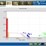
| The results are seen directly on the Terrameter screen, displaying temperature, SP, fluid resistivity and the different formation resistivities.
Export can be made to simple ASCII files for creating report figures or inclusion in other logging software. |
|
Imaging
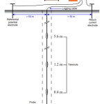
Borehole imaging is normally achieved by having two or more waterproof resistivity cables lowered into separate boreholes. Measurements are then made across the cabling to produce a pseudosection between the boreholes providing more detail on the distribution of resistivity and thus the structure of the subsurface in that area.
The waterproof cabling is the same as that used for marine surveys, thus there are two types: a dual-purpose cable that is okay for shallow boreholes (but can also be used for surface measurements) and ‘full marine’ cables which have better waterproofing, and a strengthening member within them, for deeper boreholes. The latter cables are normally too heavy to handle on-land for regular surface surveying.
The resolution is assumed to be approximately half the take-out spacing on the cable, thus providing far better resolution at depth than any surface resistivity survey. There are some considerations to be made such as ensuring the boreholes have not had metal or solid plastic liners installed as these will make measurement impossible. In addition, to create a pseudosection between two boreholes, the active length of cable within the borehole must be at least 1.5 times longer than the distance between the holes. It is possible to mix a combination of surface and borehole electrodes for even more detail.
More to read
Application areas
Methods
Resistivity and induced polarization
Case Stories
Products