When we use a set of electrodes to measure resistivity, what we actually record in the field is an apparent resistivity; this is the resistivity returned from a particular arrangement of electrodes, assuming that the volume of material being measured is completely homogenous. To move from apparent resistivity to ‘true’ resistivity, we must run the entire data set through inversion software. Apparent resistivity (ρa) is expressed in ohm-metres (Ωm).
To better understand the concept of apparent resistivity, we must consider some fundamentals of electrical theory, starting with resistance. Resistance describes how easy or hard it is for an electrical current to move through a sample of material. Lower resistance will result in more current flow and, if there is a mix of materials, the current will always take the path of least resistance. Resistance is calculated by Ohm’s Law which relates potential (voltage), current flow and resistance as: V = I x R. In a resistivity meter we measure the voltage whilst a known current flows, so we can rearrange the Ohm’s Law equation to calculate the resistance (by dividing the voltage by the current).
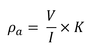
Resistance varies depending upon how much material we measure through, and we would prefer to define an intrinsic property (one which is fixed for a particular material, regardless of how much material is under test) which is why we attempt to produce models of ground resistivity. To do this, we need to consider the volume of material affecting our measurement. Apparent resistivity (ρa) takes the earth volume surrounding your electrodes in a resistivity investigation into consideration by applying a geometrical factor, Κ, to the calculated resistance:
Κ is unique to a specific pattern and spacing of electrodes and assumes a homogeneous . For a Wenner array Κ is defined as
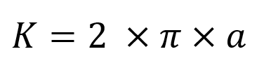
where α, is the distance between your electrodes; for other electrode arrangements the K factor will be defined differently. This effectively normalises measurements, i.e., a different arrangement of electrodes used over the same half-space might return a different resistance, but the apparent resistivities would be the same.
In a homogenous soil, the apparent resistivity is a good approximation of the resistivity but as this is quite an uncommon situation in reality, we cannot normally make interpretations from the apparent resistivity data and must run an inversion on the dataset to produce a model of what we hope to be the true distribution of resistivity within our survey area.
More to read
Application areas
https://www.guidelinegeo.com/application-areas/
Methods
https://www.guidelinegeo.com/resistivity-and-induced-polarization/
Case Stories
https://www.guidelinegeo.com/solutions/case-stories/
Products
https://www.guidelinegeo.com/abem-resistivity-seismics-tem/