Selecting the correct survey strategy for locating old building remains will depend on what type of structure you are looking for as well as how accurately you need it mapped. Is the purpose of the survey to locate and identify sturdy masonry walls or are you aiming to present a complete spatial plan of an old wooden building?
When you are planning an archaeological geophysical survey to find old building remains antenna frequencies between 160 MHz and 1000 MHz are suitable. In most cases, a frequency around 500 MHz is used, as this gives a good trade-off between depth penetration (around 4-5 meters) and resolution (around 5-6 cm).
Regardless of whether or not you use a GPS for positioning, it is always good to define a basic survey layout comprising at least a baseline and set of parallel lines to ensure complete coverage. However, most modern processing software packages can handle almost any kind of survey layout, even if the data were collected along random paths; however, a more structured approach to data collection inevitably produces the best results. So, a measuring tape or two is always good to have, plus some spray cans. And keep pen and paper ready for exceptions!
Find old wooden buildings
The primary factor that will dictate the possible success rate of mapping an older decaying wooden building is the contrast between the material you are looking for and the surrounding soils. This will differ greatly from building to building and from site to site. If the contrast isn’t sufficient, the GPR won’t “see” the features. If the conditions are right or if the wooden post holes, for example, have been stone lined, GPR can be a good solution for mapping. You need to measure densely positioned parallel profiles to maximize your chance of finding the individual building components like hearths, timber slots and post holes. A rough guide to determining a suitable profile spacing is to take the size of the smallest object you want to find and divide it by 2. Some timber building features could be quite small, and it is not rare to end up with a profile spacing of between 5-10 cm, especially when hoping to detect small post holes and/or packing stones.
Find old masonry or brick buildings
For more substantial building remains (i.e. buried masonry or brick structures) the strategy might differ slightly as you are most likely trying to detect something that is both larger and producing a stronger reflection. If the purpose is simply to verify the presence a substantial building at a site, a relatively coarse profile spacing may be sufficient. In many cases you can verify that you have substantial building remains in the data in real-time, while measuring in the field, by looking for recurring patterns of strong hyperbolas. If your end goal is to produce depth/time slices however, it is recommended to use a transect spacing of 25 cm (or at the most 50 cm) and to survey in parallel transects. If the purpose is to map the structure as thoroughly as possible, it may also be recommended to survey in two directions on top of your suspected building. If time constraints do not allow such comprehensive data collection, try to orientate your survey lines so that they run diagonally with respect to the building layout (if you know or suspect what this might be) to avoid ever running parallel with one set of wall lines. When running close to the direction of some of the wall lines, it is possible to have linear features falling entirely between survey lines or, if care is not taken in the processing, to accidentally remove some of the real features during the filtering process.
Measurements with GPS positioning
Make sure you have good GPS conditions, with a clear view of the sky, and not close to buildings or in dense forest. If the GPS provides an RTK output of high quality (fix) the GPR measurements can be done more or less as you want, depending on what you are looking for and how you are going to treat the data. But for the interpretation it is most often best to have several single parallel files, which can be compared, during interpretation or interpolated to form a 3D volume and time sliced.
|
In this example too areas are investigated with two single long profiles. If measuring like a “snake” it can be hard to compare the signature from the same object at different locations across the grid during interpretation. But time in the field is most often decreased considerably.
Note! Make sure the turns on the “snake” are outside the investigation area, to avoid creating artefacts.
Also, if a problem occurs with a data file, it will result in the loss of a larger percentage of your survey area, than having a separate file per forward/backward traverse. | 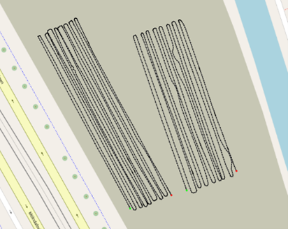 |
|
Here data are collected as single parallel profiles in two different directions. The data can easily be compared, profile to profile, in most processing software so identification and classification of the same type of signature can be made and ‘patterns’ of layout identified. | 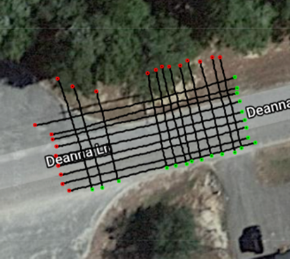 |
Measurements with no positioning
If you are going to work without any positioning, the best approach is to work in rectangular areas and with one or two baselines. When using one baseline, all profiles can start from this (or at least record their start relative to this line) and are made in the same direction. If working with one baseline, it is still good to have two measuring tapes on the ground, to guide the profile to the correct position. When using two baselines, it is easy to start and stop every second profile on baseline 1 or 2. For this type of work guide ropes along the ground are also good to use, to positions the profiles correct.
For both approaches, the area to investigate at one time should be limited to maybe 50- to 100-meter-long profiles, as longer stretches are hard to keep straight. Also make sure to keep good notes on profile names and the distance from the baseline start. This is needed if and when you need to skip a profile due to obstacles or maybe restart some profile. It can also be good to have and move along a spray can on each side of the grid, to indicate the current measurement profile position and have something to aim at whilst navigating along the traverse.
Note! If required, the ends of the baseline can be georeferenced, or located with reference to permanent features on the ground, and then the positional information can be used in the post-processing software to georeference all the profiles.
|
Here measurements are made with one single baseline. But on the ground, you have two measuring tapes, one as a baseline and one giving you the direction of the profile. All profiles start from the same base as indicated with the green dots and are made in the same direction. Note! The profiles do not need to be of the same length and, perhaps due to obstacles, you may need to skip some profiles. | 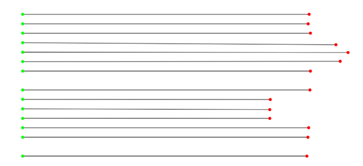 |
|
When using two base lines, the field work gets more efficient as you can measure in both directions. Care should be made on both start and stop, to get the profiles aligned as wanted. | 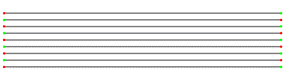 |
Results
As GPR measurements carried out to map old building remains are done in parallel profiles, often densely spaced, these data sets are excellent to use as the basis for a 3D volume. If this is the intention, then the profile spacing should not exceed 50 cm. The final 3D volume can be subdivided into depth/time slices, and this is often the primary source of your interpretation but don’t forget that there are lots of useful information in your 2D profiles as well and these should always be used to verify and strengthen your interpretation. One way of making the interpretation of your detected features even easier is to transform your depth/time slices into an animated movie. For final presentation to non-technical parties, it may be useful to apply coloring or present some form of threshold plot that highlights and/or isolates the strongest reflectors to make the layout of the structure more obvious.
More to read
Application Area
Method
Help article
Case stories
Unsealing the legendary Tomb Of Christ
The-Holy Sepulchre Case story (PDF)
Viking ship discovered in Norway